This project implements a dual-mode sensor system using an Arduino-compatible board. The system monitors distance and temperature, displays readings on an LCD, and controls a motor based on proximity detection. The button toggles between temperature and distance display modes.
What This System Does
The core functionality combines three independent subsystems:
Distance sensing with ultrasonic measurement Temperature monitoring with analog voltage conversion Motor speed control based on proximity thresholds
The LCD displays either temperature or distance depending on user input. A physical button switches between modes. The motor runs at different speeds depending on whether an object is within the defined threshold distance.
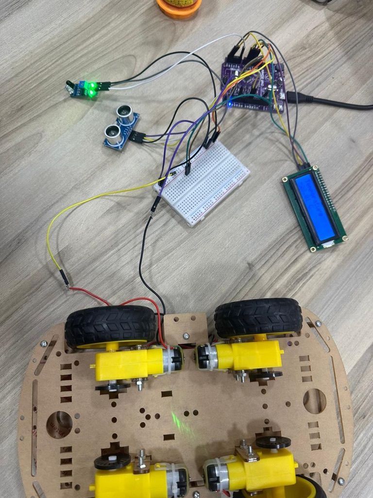
Hardware Architecture
The system uses five main components connected to the Maker UNO board:
The HC-SR04 ultrasonic sensor measures distance through time-of-flight calculation. The TRIG pin sends a 10-microsecond pulse. The ECHO pin returns a pulse whose duration is proportional to distance. The formula distance = duration / 58 converts microseconds to centimeters based on the speed of sound.
The MH-Sensor-Series Flying Fish sensor (configured as a TMP36-compatible analog temperature sensor) outputs voltage proportional to temperature. The ADC reads a value from 0 to 1023, which maps to 0V to 5V. The conversion formula (voltage - 0.5) * 100.0 accounts for the TMP36's 0.5V offset and 10mV per degree Celsius scaling.
The DC motor connects to a PWM-capable pin (pin 5). The analogWrite() function generates a pulse-width modulated signal to control speed. Two speed constants define motor behavior: SLOW_SPEED (100) when objects are close, FAST_SPEED (255) otherwise.
The QAPASS LCD uses I2C communication on address 0x27. This requires only two wires (SDA and SCL) rather than the parallel connection that standard character LCDs use. The LiquidCrystal_I2C library handles the protocol overhead.
The Maker UNO's built-in button on pin 2 uses INPUT_PULLUP mode. The pin reads HIGH when the button is not pressed and LOW when pressed. This eliminates the need for an external pull-up resistor.
Components Used
- Maker UNO Rev1.1 microcontroller board
- MH-Sensor-Series Flying Fish sensor
- HC-SR04 Ultrasonic Sensor
- DC motor (actuator)
- QAPASS LCD display module (UI display)
- Jumper wires
- Breadboard
- Power supply / USB cable for board (USB A to Micro)
Development Environment
The project was developed on macOS. The Maker UNO requires a CH340 USB-to-serial driver for macOS to recognize the board. After installing the driver, the board appears as a serial port in the Arduino IDE.
The LiquidCrystal_I2C library is required for I2C LCD communication. This library is not included in the standard Arduino installation and must be installed through the Library Manager or manually added to the Arduino libraries folder.
How the Code Works
The program structure follows a standard Arduino pattern: setup() initializes hardware, loop() executes continuously.
Setup Phase
Pin modes are configured for input and output. The ultrasonic sensor's TRIG pin is an output (sends pulses), ECHO pin is an input (receives pulses). The motor pin is configured for PWM output. The temperature sensor pin is an analog input. The button uses INPUT_PULLUP to avoid floating states.
The LCD initialization sequence calls init() and backlight(), then displays a startup message before clearing the screen.
Main Loop
The loop runs five functions in sequence:
measureDistance() sends an ultrasonic pulse and calculates distance from echo timing controlMotor() adjusts motor speed based on measured distance readTemperature() reads analog voltage and converts to Celsius checkButton() detects button presses and toggles display mode updateLCD() refreshes the screen with current sensor data
A 200ms delay at the end of each cycle prevents excessive updates and reduces flicker.
Distance Measurement
The ultrasonic ranging sequence follows the HC-SR04 datasheet timing:
- Pull TRIG low for 2 microseconds to ensure clean state
- Pull TRIG high for 10 microseconds to trigger measurement
- Pull TRIG low to complete the trigger pulse
- Read ECHO pin duration using pulseIn() with 30ms timeout
The pulseIn() function returns the duration in microseconds that the ECHO pin stayed HIGH. If no echo is received within the timeout, it returns 0. The code checks for this condition and sets distance to -1 for out-of-range readings.
The division by 58 converts microseconds to centimeters. Sound travels at approximately 340 meters per second. The pulse travels to the object and back (double the distance), so the conversion factor is (1000000 / 340 / 2) which simplifies to approximately 58.
Motor Control Logic
The motor speed depends on a simple threshold comparison:
if (distance > 0 && distance < DISTANCE_THRESHOLD) {
    analogWrite(MOTOR_SPEED_PIN, SLOW_SPEED);
} else {
    analogWrite(MOTOR_SPEED_PIN, FAST_SPEED);
}
When an object is detected within 5 cm, the motor slows to PWM value 100. Otherwise, it runs at maximum speed (255). The distance > 0 check prevents motor changes during invalid readings.
Temperature Reading
The analog sensor produces voltage that the ADC converts to a 10-bit value (0 to 1023). The code maps this to voltage, then applies the TMP36 formula:
int sensorValue = analogRead(TEMP_PIN);
float voltage = sensorValue * (5.0 / 1023.0);
temperature = (voltage - 0.5) * 100.0;
The TMP36 outputs 0.5V at 0°C and increases by 10mV per degree. Subtracting 0.5V removes the offset, then multiplying by 100 converts the voltage difference to temperature in Celsius.
Button Detection
The button handler uses edge detection to trigger only on press events, not while the button remains held:
static bool lastState = HIGH;
bool currentState = digitalRead(BUTTON_PIN);

if (lastState == HIGH && currentState == LOW) {
    showTemperature = !showTemperature;
    delay(200);
}
lastState = currentState;
The static variable persists between function calls. The code detects the HIGH-to-LOW transition, toggles the display mode, and applies a 200ms debounce delay to prevent switch bounce from registering multiple presses.
LCD Update Strategy
The display code minimizes unnecessary clears to reduce flicker:
static bool lastMode = !showTemperature;

if (lastMode != showTemperature) {
    lcd.clear();
    lastMode = showTemperature;
}
The screen only clears when switching modes. Within each mode, the code overwrites characters directly and pads with spaces to erase previous longer values. This produces a stable display without the full-screen flash that occurs with repeated lcd.clear() calls.
Why This Design Works
The system demonstrates several embedded programming principles:
State Management: The showTemperature boolean controls display mode. The button toggles this state. The LCD responds to state changes rather than constantly clearing.
Threshold-Based Control: The motor responds to a binary threshold rather than proportional control. This simplifies logic and produces predictable behavior. The system either slows down or runs at full speed. No intermediate states.
Debouncing: The 200ms delay after button detection prevents mechanical switch bounce from registering as multiple presses. This is a minimal debounce implementation sufficient for this use case.
Timeout Handling: The pulseIn() timeout prevents the program from blocking indefinitely if the ultrasonic sensor receives no echo. The code treats timeout as an error condition (distance = -1) and continues execution.
Separation of Concerns: Each subsystem (distance, temperature, motor, button, display) has its own function. The main loop orchestrates these without mixing logic. This makes the code easier to debug and modify.
Conclusion
This project demonstrates how independent hardware subsystems integrate through software coordination. The ultrasonic sensor, temperature sensor, motor, and display each operate according to their own physical principles. The microcontroller reads sensor states, applies control logic, and updates outputs.
The code structure separates measurement, control, and display concerns. Each function handles one responsibility. The main loop orchestrates timing without mixing implementation details.
Understanding how sensors convert physical phenomena to voltage, how ADCs digitize analog signals, and how PWM controls motor speed transforms this from a collection of library calls into a comprehensible system where each component's behavior follows from its physical implementation.